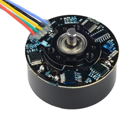
Product Description
The KIN series hollow absolute rotary encoders include single-turn and multi-turn models, supporting protocols such as RS485. Single-turn encoders offer a maximum resolution of 23 bits, while multi-turn encoders offer a maximum resolution of 65,536 turns. They feature a wide operating temperature range of -40°C to 85°C, as well as excellent vibration and shock resistance, making them suitable for servo drive control systems.

Product parameters
KIN52 Single Turn | KIN52 Multi Turn | KIN60 Single Turn | KIN60 Multi Turn | KIN71 Single Turn | KIN71 Multi Turn | |
Model | Stator Model: Rotor Model: | Stator Model: Rotor Model: | Stator Model: Rotor Model: | Stator Model: Rotor Model: | Stator Model: Rotor Model: | Stator Model: Rotor Model: |
Resolution | Maximum support 8388608 (23bit), compatible with 17bit | RS485 communication: 23-bit, compatible with 17-bit | Maximum support 8388608 (23bit), compatible with 17bit | |||
Number of revolutions | — | 65536(16bit) | - | 65536(16bit) | - | 65536(16bit) |
Auxiliary functions | Fault warning | |||||
Interface | RS485 | RS485,BISS,SSI | RS485 | |||
Communication frequency | ≤16K | |||||
Baud rate | 2.5Mbps | RS485: 2.5Mbps; | 2.5Mbps | |||
Input shaft tolerance | Radial: ±0.2mm; Axial: ±0.1mm; Axial movement: <±0.03mm | |||||
Spindle speed | ≤6000rpm | |||||
Moment of inertia | —— | ≈0.08kg·mm² | —— | |||
Weight | —— | ≈0.10kg(cable not included) | —— | |||
Rotor angular acceleration | —— | ≤80000rad/s² | —— | |||
Vibration | Between 10 and 55 Hz, maintain an amplitude of 1.5 mm; between 55 and 2000 Hz, acceleration of 98 m/s²; 2 hours per axis in X, Y, and Z directions, for a total of 6 hours | |||||
Mechanical shock | Shock acceleration: 980m/s², 11ms; 3 shocks in each direction, 18 times in total | |||||
Operating temperature | -40℃ to 85℃ | |||||
Relative humidity | ≤90% (40℃/21d, based on EN 60068-2-78); no condensation | |||||
IP rating | —(Motor rear shell protection) | |||||
Electrical Parameters
KIN52 Single-Turn | KIN60 Single-Turn | KIN71 Single-Turn | ||||||||
Specifications | Temperature T=25℃ | Temperature T=25℃ | Temperature T=25℃ | |||||||
Minimum | Typical | Maximum | Minimum | Typical | Maximum | Minimum | Typical | Maximum | ||
Supply Voltage | 4.75V | 5V | 5.25V | 4.75V | 5V | 5.25V | 4.75V | 5V | 5.25V | |
Main Power Supply Current Consumption (Typical) | — | 130mA | — | — | 150mA | — | — | 130mA | — | |
Differential Output Level | High Level | 3.5V | — | — | 3.5V | — | — | 3.5V | — | — |
Low Level | — | — | 1.7V | — | — | 1.7V | — | — | 1.7V | |
Edge Transition Time | — | — | 100ns | — | — | 100ns | — | — | 100ns | |
Insulation Resistance | 50MΩ | — | — | 50MΩ | — | — | 50MΩ | — | — | |
KIN52 Multi-Turn | KIN52 Multi-Turn | KIN71 Multi-Turn | ||||||||
Specifications | Temperature T=25℃ | Temperature T=25℃ | Temperature T=25℃ | |||||||
Minimum | Typical | Maximum | Minimum | Typical | Maximum | Minimum | Typical | Maximum | ||
Supply Voltage | 4.75V | 5V | 5.25V | 4.75V | 5V | 5.25V | 4.75V | 5V | 5.25V | |
Main Power Supply Current Draw (Typical) | — | 130mA | — | — | 150mA | — | — | 130mA | — | |
Battery Voltage | — | 3.6V | — | — | 3.6V | — | — | 3.6V | — | |
Battery Supply Current Draw (Motor Stalled) | — | 35uA | — | — | 35uA | — | — | 35uA | — | |
Battery Fault Voltage | — | 2.9V | — | — | — | — | — | 2.9V | — | |
Battery Warning Voltage | — | 3.1V | — | — | 3.1V | — | — | 3.1V | — | |
Mode transition voltage | Main power to low power mode | — | 4.2V | — | — | 4.2V | — | — | 4.2V | — |
Low power to main power mode | — | 4.3V | — | — | 4.3V | — | — | 4.3V | — | |
Differential output level | High level | 3.5V | — | — | 3.5V | — | — | 3.5V | — | — |
Low level | — | — | 1.7V | — | — | 1.7V | — | — | 1.7V | |
Edge transition time | — | — | 100ns | — | — | 100ns | — | — | 100ns | |
Insulation resistance | 50MΩ | — | — | 50MΩ | — | — | 50MΩ | — | — | |
Cable Definition

KIN52 Single-Turn / KIN71 Single-Turn
Terminal Position | 1 | 2 | 3 | 4 | 5 | 6 | 7 | 8 |
RS485 Definition | NC | NC | 485+ | 485- | NC | NC | 5V | GND |
KIN52 Multi-Turn / KIN71 Multi-Turn
Terminal Position | 1 | 2 | 3 | 4 | 5 | 6 | 7 | 8 |
RS485 Definition | NC | NC | 485+ | 485- | Battery + | Battery GND | 5V | GND |
KIN60 Single-Turn
Terminal Position | 1 | 2 | 3 | 4 | 5 | 6 | 7 | 8 |
RS485 Definition | NC | NC | 485+ | 485- | NC | NC | 5V | GND |
BISS Definition | DATA+ | DATA- | CLK+ | CLK- | ||||
SSI Definition |
KIN60 Multi-Turn
Terminal Position | 1 | 2 | 3 | 4 | 5 | 6 | 7 | 8 |
RS485 Definition | NC | NC | 485+ | 485- | Battery + | Battery GND | 5V | GND |
BISS Definition | DATA+ | DATA- | CLK+ | CLK- | ||||
SSI Definition |
[Note] PE Cable Installation Diagram:

Structure Dimensions
KIN52
Stator Dimension
Rotor Dimensions

Stator and Rotor Installation Positioning Requirements
 Recommended Installation Platform

KIN60
Stator Dimensions

Rotor Dimensions

Stator and Rotor Installation Positioning Requirements

Recommended Installation Platform

KIN71
Stator Dimensions

Rotor Dimensions

Stator and Rotor Installation Positioning Requirements

Recommended Installation Platform

Product Display

High-precision measurement capability: Single-turn measurement up to 23 bits, multi-turn measurement up to 16 bits
Multi-protocol compatibility: Supports RS485, BISS, and SSI
Strong environmental adaptability: Wide operating temperature range of -40°C to 85°C, vibration and shock resistance

Flexible mounting design: Axial or radial mounting options, compatible with shaft misalignment
Intelligent assistance: Fault warning, multi-turn low-power battery operation
Quality Control
The quality of encoders is directly related to the stability and reliability of industrial automation systems. We have built a full-process quality control system, strictly screening suppliers from raw material procurement to ensure that the performance of core components meets standards; in the production process, we use high-precision equipment and standardized processes, and cooperate with online detection technology for real-time monitoring; in the finished product stage, we conduct rigorous tests such as high and low temperature, electromagnetic compatibility, and life aging to eliminate performance risks. Each encoder has passed multiple quality inspection levels, and its excellent quality has laid a solid foundation for intelligent manufacturing, providing customers with long-term and stable use guarantees.

Application Cases
This series of encoders is mainly used in servo drive control systems, providing accurate position and speed feedback for industrial automation equipment, precision machinery and robots, ensuring system positioning accuracy and operational stability.

Installation Method
KIN52
1.Installation diagram | 2.Installation accessories |
| Phillips torque screwdriver Metric 1.5mm across-flat hexagonal torque wrench 3-M2×5.5 Phillips pan head screw + flat washer combination 2-M3×3 hexagon socket set screw with socket point 4-M1.6×6 Phillips countersunk head screw |
3.Installation sequence | |
| Radial Rotor Installation: ① Slide the encoder rotor onto the motor shaft until it is properly positioned. ② Use a hexagonal torque wrench to sequentially tighten the two M3×3 hexagon socket-point set screws. [Note]: If the rotor height needs to be adjusted, tighten the screws after adjustment. To prevent the screws from loosening, apply thread sealant to the threaded holes or use screws pre-applied with thread sealant. The recommended tightening torque is 7±0.2 kgf·cm. |
| Axial Rotor Installation: ① Slide the encoder rotor onto the motor shaft until the end faces are flush and align the four screw holes. ② Use a Phillips torque screwdriver to sequentially tighten the four screws (M1.6×6 Phillips countersunk screws). [Note]: After tightening the four countersunk screws, ensure that the screw head flatness is no higher than 0.3mm above the rotor surface; otherwise, it will interfere with the stator. To prevent the screws from loosening, apply thread sealant to the threaded holes or use screws pre-applied with thread sealant. The recommended tightening torque is 1.2±0.2 kgf・cm. |
| Stator Installation: ① Place the encoder stator on the stator mounting surface and align the three screw holes. ② Use a Phillips torque screwdriver to sequentially tighten the three screws (M2×5.5 Phillips pan head screw + flat washer). [Note]: To prevent these screws from loosening, apply thread sealant to the threaded holes or use screws with pre-applied thread sealant. The recommended tightening torque is 2.8±0.2 kgf・cm. |


KIN60
| 1.Installation diagram | 2.Installation accessories |
| Phillips torque screwdriver Metric 1.5mm across-flat hexagonal torque wrench 8-M1.6×6 Phillips countersunk head screw 4-M1.6×5 Phillips pan head screw + flat washer combination 3-M3×3 hexagon socket set screw with socket point |
| 3.Installation sequence | |
| Radial Rotor Installation: ① Slide the encoder rotor onto the motor shaft until it is properly positioned. ② Use a hexagonal torque wrench to sequentially tighten the two M3×3 hexagon socket-point set screws. [Note]: If the rotor height needs to be adjusted, tighten after adjustment. To prevent the screws from loosening, apply threadlocker to the threaded holes or use screws pre-applied with threadlocker. The recommended tightening torque is 7±0.2 kgf·cm. |
| Axial Rotor Installation: ① Slide the encoder rotor onto the motor shaft until the end faces are flush and align the eight screw holes. ② Use a Phillips torque screwdriver to sequentially tighten the eight screws (M1.6×6 Phillips countersunk screws). [Note]: After the eight countersunk screws are installed, ensure that the screw head plane is no higher than 0.5mm above the rotor surface; otherwise, interference with the stator will occur. To prevent the screws from loosening, apply threadlocker to the threaded holes or use screws pre-applied with threadlocker. The recommended tightening torque is 1.2±0.2 kgf·cm. kgf·cm. |
| Stator Installation: ① Place the encoder stator on the stator mounting surface and align the four screw holes. (M1.6×5 Phillips pan head screw + flat washer combination) [Note]: To prevent these screws from loosening, pre-apply thread sealant to the threaded holes, or use screws with pre-applied thread sealant. Recommended tightening torque: 1.2±0.2 kgf·cm. |


KIN71
| 1.Installation diagram | 2.Installation accessories |
| Phillips torque screwdriver Metric 1.5mm across-flat hexagonal torque wrench 4-M2×5.5 Phillips pan head screw + flat washer combination 2-M3×3 hexagon socket set screw with socket point 8-M1.6×6 Phillips countersunk head screw |
| 3.Installation sequence | |
| Radial Rotor Installation: ① Slide the encoder rotor onto the motor shaft until it is properly positioned. ② Use a hexagonal torque wrench to sequentially tighten the two M3×3 hexagon socket-point set screws. [Note]: If the rotor height needs to be adjusted, tighten the screws after adjustment. To prevent the screws from loosening, apply threadlocker to the threaded holes beforehand, or use screws pre-applied with threadlocker. The recommended tightening torque is 7±0.2 kgf·cm. |
| Axial Rotor Installation: ① Slide the encoder rotor onto the motor shaft until the end faces are flush, aligning the eight screw holes. ② Use a Phillips torque screwdriver to sequentially tighten the eight screws (M1.6×6 Phillips-recessed countersunk screws). [Note]: After tightening the eight countersunk screws, ensure that the screw head flatness is no higher than 0.3mm above the rotor surface; otherwise, interference with the stator will occur. To prevent the screws from loosening, apply threadlocker to the threaded holes beforehand, or use screws pre-applied with threadlocker. Recommended screw tightening torque: 1.2 ± 0.2 kgf・cm. |
| Stator Installation: ① Place the encoder stator on the stator mounting surface and align the four screw holes. ② Use a Phillips torque screwdriver to sequentially tighten the four screws (M2×5.5 Phillips pan head screw + flat washer). [Note]: To prevent these screws from loosening, apply thread sealant to the threaded holes or use screws with pre-applied thread sealant. Recommended screw tightening torque: 2.8 ± 0.2 kgf・cm. |


Calibration Procedure
1.① Ensure the encoder is powered normally.
② Short-circuit TP1 and TP2. Hold for 1 second, then release.
The green light will begin flashing at a rate of 8 times per second.
③ While the green light is flashing (within 1 minute), rotate the rotor in the same direction (at least 2.5 turns).
If the indicator light remains on, calibration is successful.
2. Indicator Status Description
Status | Indicator Light Display Mode | Status Description |
Power on | Blinks once and then turns off | Power-on initialization |
Normal operation | Solidly off | Initialization completed after power-on, no alarms |
Offline calibration in progress | Blinks 8 times/s | Calibration in progress, no alarms |
Offline calibration failed | Blinks 1 time/s | Offline calibration failed |
Offline calibration successful | Solidly on | Offline calibration successful |