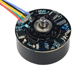
Product Description
The KON113 series encoders come in various models with high resolution, strong environmental adaptability, and stable communication performance, making them suitable for industrial scenarios such as precision machinery.

Product parameters
Product Model | KON113-M16S20SN00-HR63C0V5 | KON113-M16S23ST00-HR63C0V5 |
Output Resolution | Maximum supported: 16777216 (24-bit), 20-bit compatible | 8388608(23bit) |
Number of Revolutions | 65536 (16-bit) | |
Auxiliary Functions | Fault warning, *Electromagnetic environment warning | |
Interface | RS485 | |
Communication Frequency | ≤16K | |
Baud Rate | 2.5Mbps | |
Input Shaft Tolerance | Axial: -; Axial play: <0.1mm; | |
Spindle Speed | ≤6000rpm | |
Moment of Inertia | 8.9×10⁻⁵kg·m² | |
Weight | 0.066kg (rotor) | |
Rotor Angular Acceleration | ≤80,000rad/s² | |
Vibration | 10 to 55Hz, maintaining an amplitude of 1.5mm; | |
Mechanical Shock | Shock acceleration: 980 m/s², 11 ms; | |
Operating Temperature | -20°C to 95°C | |
Relative Humidity | ≤90% (40°C/21 days, based on EN 60068-2-78); non-condensing | |
IP Rating | —(Protected by the motor rear cover) | |
Electrical parameters
Product Model | KON113-M16S20SN00-HR63C0V5 | |||
Specifications | Temperature T=25℃ | |||
Minimum | Typical | Maximum | ||
Supply Voltage | 4.75V | 5V | 5.25V | |
Main Power Supply Current Draw (Typical) | — | 130mA | — | |
Battery Voltage | — | 3.6V | — | |
Battery Fault Voltage | — | 2.9V | — | |
Battery Warning Voltage | — | 3.1V | — | |
Mode transition voltage | Main power to low power mode | — | 4.32V | — |
Low power to main power mode | — | 4.16V | — | |
Differential output level | High level | 3.5V | — | — |
Low level | — | — | 1.7V | |
Edge transition time | — | — | 100ns | |
Insulation resistance | 50MΩ | — | — | |
Terminal and Cable Definitions

Terminal Number | 1 | 2 | 3 | 4 | 5 | 6 | 7 | 8 |
Definition | 5V | GND | 485+ | 485- | Battery + | Battery GND | NC | PE |
Cable Color | Red | Black | Blue | Yellow | Brown | White | - | Shield |
Structural Dimensions
Structural Dimensions 1

Structural Dimensions 2

Stator Mounting Hole Dimension Requirements

Rotor Mounting Shaft Dimension Requirements

Product Display

Structural Design: Non-contact (bearingless), ultra-thin reflective optical design reduces installation height.
Measurement Accuracy: Single-turn resolution ≥ 20 bits, absolute accuracy <±15 arc seconds, repeatability <±0.7 arc seconds.
Multi-turn Performance: 16-bit magnetic multi-turn design balances battery life and counting reliability.

Communication Interface: Bidirectional asynchronous communication interface.
Reliable Quality: Passed EMC and reliability testing to ensure long-term stable operation.
Ease of Use: Non-contact installation and one-click commissioning adapt to complex working conditions.
Quality Control
The quality of encoders directly impacts the stability and reliability of industrial automation systems. We have established a comprehensive quality control system, rigorously screening suppliers from raw material procurement to ensure that core components meet performance standards. During production, we employ high-precision equipment and standardized processes, coupled with real-time monitoring through online testing technology. At the finished product stage, we undergo rigorous testing for high and low temperatures, electromagnetic compatibility, and lifespan aging to eliminate performance risks. Each encoder undergoes multiple quality inspections, ensuring superior quality and a solid foundation for intelligent manufacturing, ensuring long-term, stable operation for our customers.

Application Cases
The KON113 series products are suitable for industrial servo control, precision machinery, robotics, logistics AGVs, and rail transit auxiliary systems.

Installation Instructions
| 1. Installation Jig Instructions | 2. Installation Accessories |
| Phillips Torque Screwdriver Metric 1.5mm Across-Flat Hexagon Torque Wrench |
| 3. Installation Procedure | |
| Stator Installation: ① Align the front face (electronics side) of the stator with the A-side of the mounting jig, and align the pin holes with the jig's locating pins. ② Reverse the assembled stator and jig, aligning the stator legs with the mounting platform and the jig's center hole with the mounting axis to position the stator motherboard. Secure the motherboard with five M2.5×8 Phillips-recessed small pan head screws and flat washers, applying a final tightening torque of 5-7 kgf·cm. ③ Slowly remove the jig, taking care not to tilt it. The stator is now installed. [Notes]: 1) Pay attention to the screw head height, especially at the star mark "*." The height of the screw head protruding from the PCB must be less than 2.3mm. 2) To prevent the screws from loosening, pre-apply threadlocker to the threaded holes or use screws with pre-applied threadlocker. |
| Rotor Installation: ① Align the back of the rotor (not the encoder) with the B side of the mounting jig. Be mindful of the impact of the magnets during attraction, and align the rotor shaft hole as closely as possible with the jig shaft hole. ② Reverse the assembled rotor and jig, aligning the rotor shaft hole with the mounting shaft. Slowly push the jig downward, keeping the jig flat and parallel to the mounting platform. Stop when the jig legs are aligned with the mounting platform. Be careful not to push the rotor too far. Use two M3×3 hexagon socket head set screws with a torque of 7 kgf/cm to tighten the rotor to the shaft. (Be mindful of the effect of the rotor magnet's attraction on the screws and tools to avoid contact and damage to the encoder.) ③ Remove the jig. Rotor installation is complete. After rotor installation, rotate the rotor one full revolution to check for interference, paying particular attention to the screws on the bottom of the encoder. Remove the encoder protective film and clean the encoder surface with a cotton swab or dust-free cloth. After installation, proceed to the next step of testing. |


4. Precautions
This encoder has a split-body design. The encoder shaft (including the code disc) is separate from the main unit.
The encoder shaft and motor shaft must be exposed to air during installation. Please assemble in a clean, dust-free environment.
Before installation, degrease and clean the motor shaft to prevent oil and dirt from interfering with the encoder shaft's tightness and contaminating the code disc.
Be careful not to touch the code disc directly with your hands or other hard objects. Fingerprints, oil, dust, and other debris can cause signal abnormalities, and hard objects can damage the code disc.
After installation, inspect the surface of the reflective code disc for cleanliness.
If contamination is detected, gently wipe it with a dust-free cloth or other material dipped in alcohol.
Please note that excessive force or use of hard materials may damage the code disc.
Communication Protocol
1. Overview
Unit | Descriptio | Notes |
Communication code system | Binary | — |
Communication circuit | Differential drive | RS485 |
Data transmission content | Single-turn position information | 23bit |
Multi-turn position information | 16bit | |
Communication rate | 2.5 Mbps | — |
2. E²PROM Communication Specifications
Unit | Address | Description | Notes |
Read/Write User Parameter Address Range | 0-0x7E | User parameter range | This address field can be used to store user parameters. Some areas are reserved and are not recommended for use. |
Page Address | 0x7F | 0~7 | Do not exceed this range. |
Maximum Erasable and Writeable Endurance | 100,000 times | — | Number of times the operation can be performed |
3. Frame Format
Each data frame consists of several data words. The transmission and reception of each data word is implemented by a start bit, 8 data bits, and a stop bit, with the least significant bit first and the most significant bit last.
The terms used in data frame transmission are shown in the following table:
Unit | Description | Notes |
CF | Control Field | This section identifies different command types. |
SF | Status Field | This section is used to obtain encoder status. |
DF | Data Field | Encoder position data. |
ADF | Address Field | Accessible encoder addresses. |
EDF | E2PROM Field | Contents at the address. |
CRC | CRC Check | Polynomial: x8+1 (Except CRC, all data are XORed). |
 4. Detailed Description
4.1 Control Field (CF)
The CF consists of one data word. The types and contents are shown in the following table:
CF Class | CF Type | Notes |
Read Data | ID0(0x02) | Reading Absolute Position Information (CF+SF+ABS+CRC) |
ID1(0x8A) | Reading Multi-Turn Data (CF+SF+ABM+CRC) | |
ID2(0x92) | Reading Encoder ID Information (CF+SF+ID+CRC) | |
ID3(0x1A) | Reading All Data (CF+SF+ABS+ID+ABM+ALMC+CRC) | |
Write E²PROM | ID6(0x32) | 8-bit "user data" can be written to the specified address. The encoder will respond within 20μs after the command format is sent. Do not communicate with the encoder during this process. |
Read E²PROM | IDD(0xEA) | 8-bit "user data" can be read from the specified address. The encoder will respond within 20μs after the command format is sent. Do not communicate with the encoder during this process. |
Reset | ID7(0xBA) | This reset command requires 10 consecutive commands at intervals of no less than 62.5μs to reset all fault flags. |
ID8(0xC2) | This reset command requires 10 consecutive commands at intervals of no less than 62.5μs to reset any single-turn position to zero (the reset data is retained after power cycle). | |
IDC(0x62) | This reset command requires 10 consecutive commands at intervals of no less than 62.5μs to reset multi-turn data to zero (does not affect single-turn data) and reset all fault flags. |
4.2 Status Field (SF)
The SF consists of one byte. The definition of each bit is shown in the following table:
Bit Field | Definition | Description |
Bit0 | Rsvd | “0” |
Bit1 | Rsvd | “0” |
Bit2 | Rsvd | “0” |
Bit3 | Rsvd | “0” |
Bit4 | Counting Error | Same as ALMC.Bit2 |
Bit5 | Xor Multi Error | Equal to the logical OR of ALMC.Bit5, Bit6, and Bit7 |
Bit6 | Rsvd | “0” |
Bit7 | Rsvd | “0” |
4.3 Data Field (DF0-DF7)
Depending on the CF type, the number of bytes in the DF field varies, as shown in the following table:
CF Type | DF0 | DF1 | DF2 | DF3 | DF4 | DF5 | DF6 | DF7 |
ID0 (0x02) | ABS0 | ABS1 | ABS2 | |||||
ID1 (0x8A) | ABM0 | ABM1 | ABM2 | |||||
ID2 (0x92) | ENID | |||||||
ID3 (0x1A) | ABS0 | ABS1 | ABS2 | ENID | ABM0 | ABM1 | ABM2 | ALMC |
ID7 (0xBA) | ABS0 | ABS1 | ABS2 | |||||
ID8 (0xC2) | ABS0 | ABS1 | ABS2 | |||||
IDC (0x62) | ABS0 | ABS1 | ABS2 |
4.4 Fault Description
ALMC Fault Bit Definition Table
Bit | 0 | 1 | 2 | 3 | 4 | 5 | 6 | 7 |
Definition | Over-speed | "0" | Counting Error | "0" | "0" | Multi-turn error | Battery error | Battery alarm |
Fault Flag Bit Description Table
Fault name | Functional Description | Solution |
Over-speed | In 5V power mode, the speed is greater than 7200 RPM. | Recycle power |
Counting Error | Single-lap information resolution failure. | Recycle power |
Multi-turn error | Multi-lap data loss, multi-lap counting failure. | Reset fault |
Battery error | Battery voltage is below 2.9V, set. | Check battery circuit and replace battery |
Battery alarm | Battery voltage is below 3.1V, set. | Replace battery and voltage is normal |
Timing Description
1. Timing Diagram

2. Detailed Specifications
Characteristic | Symbol | Minimum | Default | Maximum | Unit | Note |
Power-On time | Tpon | 450 | 550 | ms | ||
Command cycle period | Tcyc | 62.5 | μs | |||
Data byte time | Tb | 4 | μs | |||
Encoder enable delay time | Ten1 | 1.5 | 3.5 | μs | ||
Ten2 | 4.5 | μs | ||||
Encoder EEPROM | Tee | 12 | μs | Read:3bytes data; | ||
Command time | 16 | μs | Write: 4 bytes data | |||
Encoder response time | Tres | 4*N | μs | N bytes data | ||
Encoder data set-up delay time | Tset1 | 0.8 | 2 | μs | ||
Tset2 | 1 | 1.5 | μs | |||
Encoder disable delay time | Tdis1 | 0.6 | 1.2 | μs | ||
Tdis2 | 1.3 | μs |