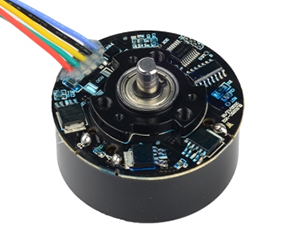
Product Description
Compact flange-mounted absolute encoders offer a variety of outputs, excellent vibration resistance, and IP65 protection. Widely used for precise position and angle measurement in AGVs, construction machinery, solar tracking, automated production lines, and other applications, they are suitable for harsh industrial environments.

Product parameters
Mechanical Data | Compliant with standards | ||
Material | Housing: Aluminum | CE certified | Yes |
Flange: Aluminum | Interference emission | EN61000-6-4 | |
Shaft: Stainless steel | Anti-interference | EN61000-6-2 | |
Shaft Load | Axial: Maximum 80N | Complies with ISO9001:2015 quality management system requirements | |
Protection Rating | IP65 | ||
Starting Torque | ≤ 0.5Nm at 25°C | CANopen encoder complies with DS301 V4.02 standard | |
Maximum Speed | 6000 RPM | Supports device protocol DS406 V3.2 | |
Shock | ≤ 100g, 3ms | Supports device protocol DS305 (LSS) | |
Vibration | ≤ 10g (10Hz-2000Hz) | ||
Weight | ≈ 500g | ||
Operating Temperature | -40°C-+80°C | ||
Storage Temperature | -40°C-+85°C | ||
Electrical Data | ||||
Interface type | SSI | CANopen | RS485/Modbus RTU | 4-20mA, 0-5/10V |
Output code | Gray code or binary code | Binary code | ASCII/Hexadecimal | Analog |
Output circuit | RS422-compliant line driver | Compliant with ISO11898 standard, optocoupler electrical isolation | Compliant with RS485 standards. Optocoupler electrical isolation. | — |
Clock frequency | 100 kHz - 1 MHz | 10K-1MHz | 4800-115200 bps | — |
Operating voltage | 10 - 30 VDC, polarity protected | |||
No-load current | ≤ 80 mA | |||
Repeat accuracy | ± 1 bit (actual accuracy depends on installation accuracy and shaft concentricity) | |||
Resolution | Single-turn resolution ≤ 13 bits (8192); multi-turn resolution ≤ 12 bits (4096) | |||
Counting direction | When connected to VCC: counterclockwise rotation relative to the shaft increases; when connected to 0V: clockwise rotation increases | |||
External set | A short-circuit with VCC activates the bit. Short-circuit duration > 100 ms | |||
Interface Type and Wiring Definitions
Interface Type: SSI (Synchronous Serial Interface)
Clock/Data: Four-wire RS422 mode, ±5V, one pair of clock triggers and one pair of data outputs.

D₁…Dₙ = Position data MSB = Most significant data bit (first data bit) LSB = Least significant data bit (last data bit) | T = 1/f (clock period ≤ 1MHz) Tp = Clock gap > Monostable trigger time Tm = Monostable trigger time (10µs–30µs |
Wiring Definition: SSI
Signal | VCC | 0V | Clock+ | Clock- | Data+ | Data- | P-set | Dir |
Cable | Brown | White | Green | Yellow | Gray | Pink | Blue | Red |
1. P-set External Set Line:
Single-turn encoder: When short-circuited with VCC, the current position data output is the zero point of the entire data set (midpoint can be customized);
Multi-turn encoder: When short-circuited with VCC, the current position data output is the midpoint of the entire data set (zero point can be customized);
2. Dir Count Direction Line: When connected to VCC, data increases counterclockwise relative to the shaft; when connected to 0V, data increases clockwise.
3. Shield Line (Shield): Internally connected to the housing by default
Interface Type: CANopen Communication Interface
Based on the CANopen communication protocol, a standard of the CIA International CAN Organization, the communication frequency is up to 1MHz.
Supports the latest CANopen communication protocol, compliant with the DS301 V4.02 standard. It also supports device-specific protocols, such as the encoder protocol DS406 V3.2.
Node address and baud rate configuration can be set using the rotary switches on the rear cover. DS305 (LSS) functionality is also supported.
Operating modes include polling, cyclic, and synchronous. Resolution, set values, limit switch values, and other additional parameters can be programmed via CANbus. All programmed parameters are stored in flash memory to prevent loss during power outages and are reloaded upon device power cycle.
Position, speed, voltage, temperature, operating range status, and cam status can be combined into freely applicable PDOs (PDO mapping).
Supported message types include LMT, NMT, SDO, PDO, SYNC, and EMCY. Using the EDS file (Electronic Data Sheet Configuration File) provided by AYAN, the rotary encoder can be easily calibrated and programmed in the configuration software of various controllers.
Wiring Definition: CANopen
Signal | VCC | 0V | Clock+ | Clock- | Data+ | Data- | P-set | Dir |
Cable | Brown | White | Green | Yellow | Gray | Pink | Blue | Red |
Note: Supports device protocol DS305 (LSS)
Interface Type: Modbus RTU Communication Description
Baud Rate: 4800bps, 9600bps, 19200bps, 38400bps, 115200bps.
Frame Format: 8 data bits, 1 stop bit, even parity, no control flow.
1. Message Format
Command Word 04H: Read Measurement Value | Master Request: Address, Command Word, Data Address, Data Length, Check Code |
Slave Response: Address, Command Word, Byte Length, Data Information, Check Code | |
Command Word 06H: Set Command | Master Request: Address, Command Word, Data Address, Data Length, Check Code |
Slave Response: Address, Command Word, Byte Length, Parameter Value, Check Code |
2. Communication Protocol between Master and Slave Devices
Each data frame sent by the master should contain the following information (in hexadecimal):
Slave Address, Command Word, Information Word, Checksum
Slave Address (1 byte): The slave device number. The master uses the slave address to identify the slave device with which it is communicating. This indicates that the slave with the user-set address will receive information sent by the master. In a Modbus network, each slave must have a unique address code, and only slaves with the address code matching the given code can respond.
Command Word (1 byte): The function code sent by the master, instructing the slave to perform a task. Information word (N bytes): Contains the data address, data length, and data information used in communication between the two devices.
Checksum (2 bytes): Used to detect data communication errors, using the Modbus CRC16 cyclic redundancy check.
Interface Type: RS485 Communication Description
Baud Rate: 4800bps, 9600bps, 19200bps, 38400bps, 115200bps.
Frame Format: 8 data bits, 1 stop bit, no parity check, no control flow.
1. When the encoder is in active mode, it actively sends data to the host computer. The data length is 16 bits in hexadecimal ASCII code, in the format: YAB>±DATA↙, i.e.:
1 | 2 | 3 | 4 | 5 | 6 | 7 | 8 | 9 | 10 | 11 | 12 | 13 | 14 | 15 | 16 |
Y | Address | > | ± | DATA | ↙ | ||||||||||
Where "Y" is the leading letter, > is the delimiter, and ± is the sign bit; DATA is the data (ASCII format, 10 bits, range -9,999,999,999 to +9,999,999,999); and the last character is a carriage return (0D).
2. When the encoder is in passive mode (question-and-answer mode): The host computer sends a query command to the encoder. The command is a 4-digit hexadecimal ASCII code in the format: A+AB↙ (AB is the encoder address, ranging from 0 to 99). The data format of the encoder's response to the host computer is the same as the data sent in active mode.
Wiring Definition: RS485 and Analog
Signal | VCC | OV | 485 A | 485 B | P-set | Analog + | Set-Allow | Analog - |
Cable | Brown | White | Green | Yellow | Gray | Pink | Blue | Red |
1. P-set External Set Line: Set base point. The set value can be selected using the configuration software (Client V2.0);
2. Set-Allow Set Allow Line: When the operating power supply VCC is applied, the baud rate defaults to 19200 bps. Function parameters are configurable;
3. Shield Line: Internally connected to the housing by default.
Product Display

Compact and Rugged: Compact aluminum housing with IP65 protection withstands tight spaces and harsh operating conditions.
True Multi-Turn Memory: Mechanical gear mechanism with battery-free 4096-turn memory ensures permanent and reliable data.
High-precision positioning: 13-bit single-turn resolution, accurate and stable measurement.

Rich Interfaces: Supports multiple industrial protocols including CANopen, SSI, RS485, and analog, ensuring strong compatibility.
Rugged and Durable: Can withstand 150N load, withstand 100g vibration, and adapt to high-speed applications up to 6000RPM.
Easy Debugging: Adjustable zero point and direction make installation simple.
Quality Control
The quality of encoders directly impacts the stability and reliability of industrial automation systems. We have established a comprehensive quality control system, rigorously screening suppliers from raw material procurement to ensure that core components meet performance standards. During production, we employ high-precision equipment and standardized processes, coupled with real-time monitoring through online testing technology. At the finished product stage, we undergo rigorous testing for high and low temperatures, electromagnetic compatibility, and lifespan aging to eliminate performance risks. Each encoder undergoes multiple quality inspections, ensuring superior quality and a solid foundation for intelligent manufacturing, ensuring long-term, stable operation for our customers.

Application Cases
This product is widely used in steering and navigation for engineering vehicles, AGVs, and sweepers; precision positioning in logistics warehousing and automotive production lines; and angle feedback for solar tracking systems. It is also suitable for non-explosion-proof industrial scenarios such as radar angle measurement, speed, and tilt sensing, providing reliable position detection for automated equipment.