

Product Description

Product parameters
Model
Parameter | AD-JH17-51-2EC | AD-JH17-101-2EC | AD-JH14-51-2EC | AD-JH14-101-2EC | AD-JH11-51-2EC | AD-JH11-101-2EC | |
Motor Parameters | Rated Voltage | 24V (Supports 24–48V) | 24V (Supports 24–48V) | 24V (Supports 24–48V) | |||
Rated Torque | 16NM | 24NM | 5.4NM | 7.8NM | 3.2NM | 4.8NM | |
Peak Torque | 24NM | 54NM | 18NM | 28NM | 7.8NM | 10.5NM | |
Rated Speed | 40rpm | 20rpm | 40rpm | 20rpm | 40rpm | 20rpm | |
Maximum Allowable Speed | 60rpm | 30rpm | 60rpm | 30rpm | 60rpm | 30rpm | |
Motor Characteristics | Number of Pole Pairs | 10 | 10 | 7 | |||
Reduction Ratio | 51:1 | 101:1 | 51:1 | 101:1 | 51:1 | 101:1 | |
Phase Inductance | 107uh (@25°C) | 170uH (@25°C) | 538uH (@25°C) | ||||
Phase Resistance | 0.16Ω (@25°C) | 0.243Ω (@25°C) | 1.1Ω (@25°C) | ||||
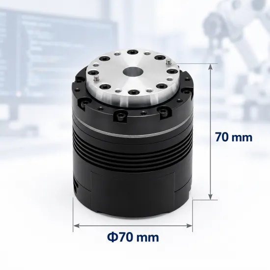
Dimensions & Weight | Outer Diameter | 80mm | 70mm | 52mm | |||
Height | 70mm | 70mm | 60mm | ||||
Motor Weight | Approx. 985g | Approx. 775g | Approx. 345g | ||||
Encoder | Encoder Resolution | 17-bit | 17-bit | 17-bit | |||
Number of Encoders | 2 | 2 | 2 | ||||
Communication | Control Interface | CAN@5Mbps (Max) | CAN@5Mbps (Max) | CAN@5Mbps (Max) | |||
Parameter Configuration Interface | UART@921600bps | UART@921600bps | UART@921600bps | ||||
Product Views

High-Precision Harmonic Drive
The robot joint actuator utilizes a precision harmonic reducer, it delivers low backlash, high transmission accuracy, and excellent repeatability, meeting the precise motion control requirements of robotic joints.

Dual-Encoder Closed-Loop Control
Dual encoders provide real-time feedback from both the motor and output shaft, enabling more accurate position control and motion compensation while improving system stability and control accuracy.

Integrated Lightweight Design
The motor, harmonic reducer, driver, and encoders are integrated into a single compact module, reducing weight and facilitating lightweight robot design.

Intelligent Communication & Safety Protection
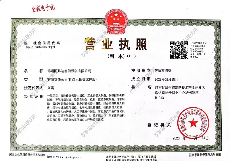
The robot joint actuator supports high-speed CAN/CAN FD communication, online parameter configuration, and firmware upgrades. Built-in temperature monitoring and protection functions ensure long-term stable system operation.
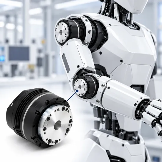
Application Cases

Quadruped Robots

Biped Robots

Robotic Arms
Interface & Wiring Description
Item Name - No. | Interface Identification | Description |
Motor Status Indicator - 1 |
| Red LED ON: The motor is in the disabled state (default state after power-up); Green LED ON: The motor is in the enabled state; Red LED Flashing: A motor fault is detected. Refer to the feedback information to identify the fault type; Green LED Flashing: The motor failed the power-on self-check. Please save the startup log information and contact customer support.
|
Terminal Resistor Switch - 2 |
| The motor is equipped with a built-in terminal resistor, which is disabled by default. |
Debug Serial Port - 3 |
| Connect the motor to a PC via a GH1.25 3-pin cable using a USB-to-CAN debugging tool (or a general USB-to-Serial adapter). The Debug Assistant software can be used for parameter configuration, firmware upgrades, and other debugging operations. |
Power Connector - 4 (with CAN Communication Terminal) |
| 1. Connect the power supply through an XT30 (2+2)-F power connector. The rated voltage is 24V for motor power input. 2. Connect external control devices through the CAN communication terminals to receive CAN control commands and transmit motor status feedback. 3. The motor is equipped with two power connectors. Either connector can be used independently, or multiple motors can be connected in series to simplify cable routing. |
Power Connector - 5 (with CAN Communication Terminal) |