Classification and Requirements of Motor Drive Systems Commonly Used in Industrial Robots
A robot's electric servo drive system is an actuator that uses the torque and force generated by various electric motors to directly or indirectly drive the robot body to achieve various movements.
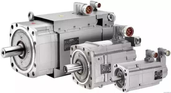
For motors driving the joints of industrial robots, the requirements are a maximum power-to-weight ratio and torque-to-inertia ratio, high starting torque, low inertia, and a wide and smooth speed range. Especially for robot end effectors (grippers), motors with the smallest possible size and mass should be used. When rapid response is required, servo motors must have high reliability and stability, and a large short-term overload capacity. These are prerequisites for the application of servo motors in industrial robots.
I. Main Requirements for Robot Joint Drive Motors
1. Speed
The time from receiving a command signal to completing the required working state should be short. The shorter the response time to the command signal, the higher the sensitivity of the electric servo system and the better the rapid response performance. Generally, the electromechanical time constant of the servo motor is used to describe its rapid response performance.
2. High Starting Torque-to-Inertia Ratio
When driving a load, the robot's servo motor is required to have a high starting torque and a low moment of inertia.
3. Continuity and Linearity of Control Characteristics
The motor speed can change continuously with the control signal, and sometimes it needs to be proportional or approximately proportional to the control signal.
4. Wide Speed Range
It can be used in a speed range of 1:1000 to 10000.
5. Small Size, Light Weight, and Short Axial Dimensions
6. Able to Withstand Harsh Operating Conditions
It can perform very frequent forward and reverse rotation and acceleration/deceleration, and can withstand overload for short periods.
Currently, due to the widespread use of AC and DC servo motors with high starting torque, high torque, and low inertia in industrial robots, most industrial robots with a load of less than 1000N (equivalent to 100kgf) use electric servo drive systems. The joint drive motors used are mainly AC servo motors, stepper motors, and DC servo motors.
Among them, AC servo motors, DC servo motors, and direct drive motors (DD) all use closed-loop position control and are generally used in high-precision, high-speed robot drive systems. Stepper motor drive systems are mostly suitable for small, simple open-loop robot systems where high precision and speed requirements are not critical. AC servo motors, due to their electronic commutation and lack of commutation sparks, are widely used in flammable and explosive environments. The power range of robot joint drive motors is generally 0.1–10 kW.
II. Motors Used in Robot Drive Systems
The motors used in industrial robot drive systems can be broadly categorized as follows:
1. AC Servo Motors
Including synchronous AC servo motors and reactive stepper motors.
2. DC Servo Motors
Including low-inertia permanent magnet DC servo motors, printed winding DC servo motors, high-inertia permanent magnet DC servo motors, and coreless armature DC servo motors.
3. Stepper Motors
Including permanent magnet induction stepper motors.
Speed sensors often use tachogenerators and rotary transformers; position sensors often use photoelectric encoders and rotary transformers. In recent years, foreign robot manufacturers have been using a hybrid photoelectric position sensor that integrates the functions of a photoelectric encoder and a rotary transformer. The servo motor can be combined with position and speed detectors, brakes, and reduction mechanisms to form a servo motor drive unit.
Robot drive systems require transmission systems with small backlash, high rigidity, high output torque, and a large reduction ratio.
III. Commonly Used Reduction Mechanisms
RV Reduction Mechanism;
Harmonic Reduction Mechanism;
Cycloidal Pinwheel Reduction Mechanism;
Planetary Gear Reduction Mechanism;
Backlash-Free Reduction Mechanism;
Worm Gear Reduction Mechanism;
Ball Screw Mechanism;
Metal Belt/Tooth Reduction Mechanism;
Ball Reduction Mechanism.
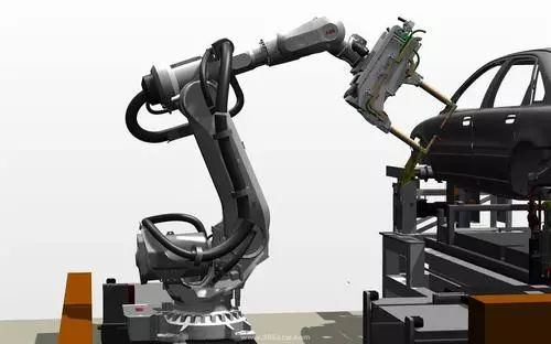
The principle of industrial robot motor drive is shown in the figure:
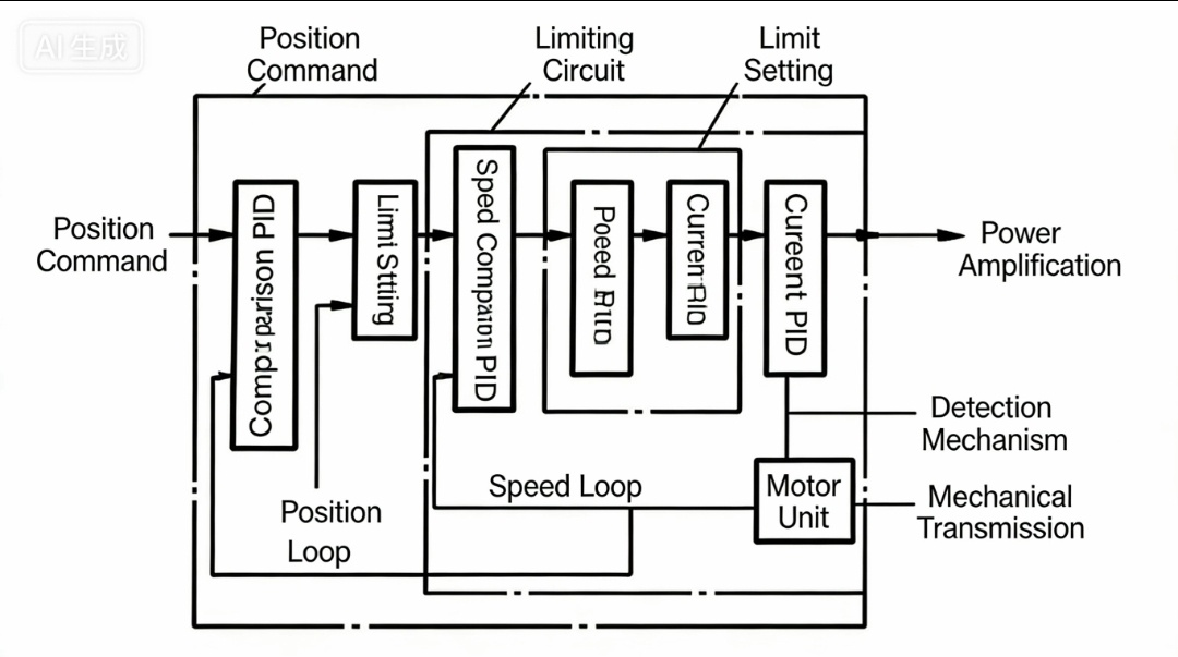
The general structure of an industrial robot electric servo system consists of three closed-loop control loops: current loop, speed loop, and position loop. Currently, many foreign motor manufacturers have developed drive products compatible with AC servo motors. Users choose different servo control methods based on their specific functional requirements. Generally, AC servo drives can achieve the following functions by manually setting their internal parameters:
Position control;
Speed control;
Torque control;
Hybrid position and speed control;
Hybrid position and torque control;
Hybrid speed and torque control;
Torque limiting;
Alarm for excessive position deviation;
Speed PID parameter setting;
Speed and acceleration feedforward parameter setting;
Zero drift compensation parameter setting;
Acceleration/deceleration time setting, etc.
IV. Types of Drivers
1. DC Servo Motor Drivers
DC servo motor drivers mostly use pulse width modulation (PWM) servo drivers. By changing the pulse width, the average voltage applied across the motor armature is altered, thereby changing the motor speed.
PWM servo drivers are characterized by wide speed range, good low-speed characteristics, fast response, high efficiency, and strong overload capacity, and are often used as DC servo motor drivers in industrial robots.
2. Synchronous AC Servo Motor Drivers
Compared to DC servo motor drive systems, synchronous AC servo motor drivers have advantages such as high torque-to-inertia ratio, no brushes, and no commutation sparks, and are widely used in industrial robots.
Synchronous AC servo motor drivers typically employ current-mode pulse width modulation (PWM) phase inverters and multi-closed-loop control systems with a current loop as the inner loop and a speed loop as the outer loop to achieve current control of a three-phase permanent magnet synchronous servo motor. Based on its working principle, drive current waveform, and control method, it can be divided into two types of servo systems:
(1) Permanent magnet AC servo system driven by rectangular wave current.
(2) Permanent magnet AC servo system driven by sinusoidal wave current.
Permanent magnet AC servo motors driven by rectangular wave current are called brushless DC servo motors, and permanent magnet AC servo motors driven by sinusoidal wave current are called brushless AC servo motors.
3. Stepper Motor Driver
A stepper motor is a component that converts electrical pulse signals into corresponding angular or linear displacement. Its angular and linear displacements are proportional to the number of pulses, while its rotational or linear speed is proportional to the pulse frequency. Within the load capacity range, these relationships do not change due to fluctuations in power supply voltage, load size, or environmental conditions, and errors do not accumulate over time. Stepper motor drive systems can adjust speed within a wide range by changing the pulse frequency, achieving rapid start-up, forward and reverse braking. As an open-loop digital control system, it is widely used in small robots. However, due to its poor overload capacity, relatively small speed range, pulsation at low speeds, and imbalance, it is generally only used in small or simple robots.
4. Direct Drive
A direct drive (DD) system is one where the motor and the load it drives are directly coupled together, without any intermediate reduction gear.
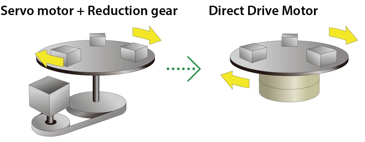
Compared to traditional electric motor servo drives, DD drives reduce the reduction gear mechanism, thereby reducing the backlash and looseness generated during system transmission, greatly improving robot precision. It also reduces the decrease in robot control precision caused by friction and torque pulsation in the reduction gear mechanism. Due to these advantages, DD drives offer good mechanical rigidity, enabling high-speed and high-precision movements. They also feature fewer components, simpler structure, easier maintenance, and higher reliability, making them increasingly important in high-precision, high-speed industrial robot applications.
The key component of DD drive technology is the DD motor and its driver. It should possess the following characteristics:
(1) High output torque: 50 to 100 times the output torque of a servo motor in traditional drive methods.
(2) Low torque pulsation: The torque pulsation of a DD motor can be suppressed to within 5% to 10% of the output torque.
(3) High efficiency: Compared to motors with reasonable impedance matching (in traditional drive methods), DD motors operate under conditions of poorer power conversion. Therefore, the larger the load, the more likely a larger motor is to be selected.
Currently, DD motors are mainly divided into variable reluctance type and variable reluctance hybrid type, with the following two structural forms:
(1) Variable reluctance DD motor with dual stator structure;
(2) Variable reluctance hybrid DD motor with central stator structure.
5. Special Actuators
(1) Piezoelectric Actuators
As is well known, strain gauge accelerometers and ultrasonic sensors have been manufactured using the electrical or electrostrictive phenomena of piezoelectric elements. Piezoelectric actuators utilize electric field energy to control displacements from a few micrometers to hundreds of micrometers with forces exceeding the micrometer level. Therefore, piezoelectric actuators are generally used in special-purpose microrobot systems.
(2) Ultrasonic Motors
(3) Vacuum Motors
Vacuum robots used in ultra-clean environments, such as ultra-vacuum robots used for handling semiconductor silicon wafers.
Source: Online Public Resources