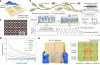
Introduction to Wheeled Robot Chassis Suspension
The wheeled robot chassis suspension is a crucial component connecting the wheels and the chassis. Its main function is to mitigate the impact of uneven ground on the chassis, ensuring good wheel-to-ground contact and improving the robot's stability and maneuverability. The following is an introduction to wheeled robot chassis suspension:
1. Types of Suspension
Non-independent Suspension:The two wheels are connected by a single axle, which is then connected to the chassis via a suspension system. Its structure is simple, but an impact on one wheel can affect the other, resulting in a larger tilt angle. It can adapt to some uneven terrain.
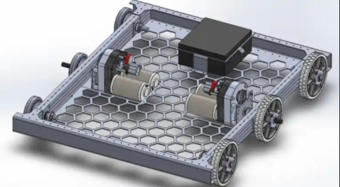
Independent Suspension: Each wheel is connected to the chassis via an independent suspension system. Independent suspension allows the two wheels to move independently, reducing mutual interference and improving driving stability, especially on uneven surfaces.
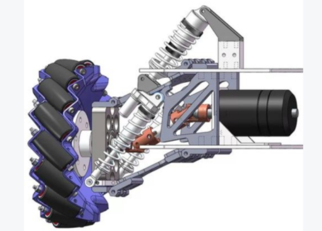
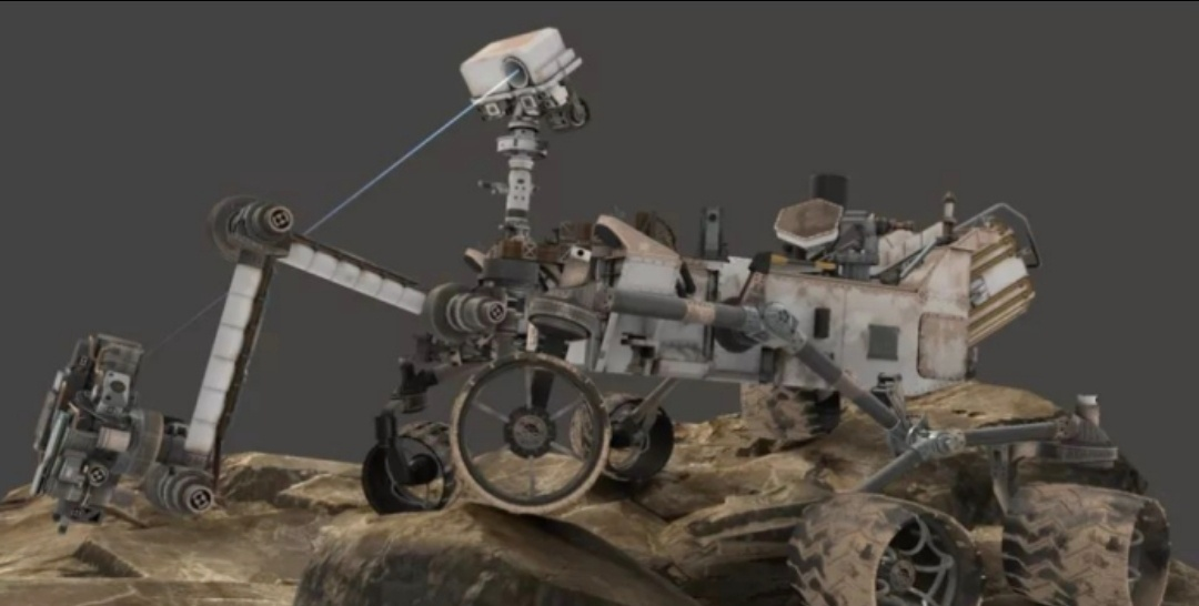
Special Suspension: Such as the Rocker-Bogie suspension system, its rocker arm and balance frame linkage design allows the robot to traverse obstacles more than twice the wheel height. Its full-wheel contact design provides excellent grip and handling performance on complex terrain.
2. Suspension Structure
Elastic Elements: Such as springs and rubber blocks, their main function is to absorb ground impact energy and dampen vibrations.
Shock Dampers: Used to attenuate the vibrations from the rebound of the elastic elements, allowing the wheels to quickly regain stability. Common types include hydraulic shock absorbers and pneumatic shock absorbers.
Guiding Mechanisms: Used to guide the wheels along a specific trajectory while transmitting force and torque.
Connecting Components: Such as bolts, nuts, and hinges, used to connect various components together, ensuring the structural strength and reliability of the suspension system.
3. Functions of Suspension
Cushioning and Shock Absorption: Reduces the impact of uneven ground on the robot chassis and internal equipment, protecting the robot's hardware systems.
Improving Stability: Maintains good contact between the wheels and the ground, providing sufficient traction to ensure the robot does not slip or lose control due to uneven ground during operation.
Enhancing Ability to Traverse: Helps the robot adapt to various complex terrains, such as crossing obstacles and traversing rough roads.
Improving Maneuverability: Optimizes the wheel's motion trajectory, making the robot's steering, braking, and other operations more sensitive and accurate, improving the robot's maneuverability.
4. Recommended Chassis Suspension Structure Durability Verification Scheme
Dynamic Load Fatigue Test
Verifies the structural stability and fatigue life of the chassis under rated load and overload conditions, and evaluates the withstand capability of the frame, connectors, and transmission components;
Test Parameters: Rated load, overload load (120% of rated load), number of loading cycles (10⁵ times), loading frequency (5Hz±1Hz);
Test Procedure: The chassis is rigidly fixed to the test bench. A vertical dynamic load is applied through a load simulation device. After every 10⁴ cycles, the machine is stopped and the appearance is inspected (for cracks, deformation, and loosening). After the test, the permanent deformation and elastic recovery rate of the structure are evaluated;
Acceptance Criteria: After the cycle, the chassis shows no cracks or plastic deformation, the loosening of connectors is ≤0.5mm, and the transmission mechanism operates smoothly without jamming.
Walking System Durability Test
Evaluates the long-term wear resistance and performance degradation of wheels, bearings, drive motors, and reducers.
Test Parameters: Simulated road surface (alternating cement, gravel, and asphalt), walking speed (80% of rated speed, constant speed), cumulative walking time (200 hours), load (rated load);
Test Procedure: Place the chassis on the composite test road surface, set to continuous walking mode, and stop every 24 hours to check wheel wear, bearing temperature (≤70℃), motor speed stability, and reducer noise (≤75dB).
Acceptance Criteria: After 200 hours of cumulative walking, wheel wear depth ≤2mm, no surface cracks; motor torque attenuation ≤10%, no oil leakage from the reducer, and walking speed fluctuation ≤±5%.
Impact and Vibration Durability Test
Impact Test: According to GB/T Standard 2423.5 uses a half-sine wave pulse with an impact acceleration of 150 m/s² and a pulse duration of 6 ms. Three impacts are applied in each of the positive and negative X, Y, and Z axes (a total of 18 impacts). After testing, the integrity of the chassis structure, the tightness of components, and functional effectiveness are checked. The passing standard is no cracks, no looseness, and normal function after power-on.
Vibration Test: Divided into sweep frequency durability and random vibration tests. Frequency sweep durability was tested according to GB/T 2423.10 standard, with a frequency range of 5Hz to 500Hz, vibration amplitude of 0.5mm, acceleration of 10m/s², and a scanning speed of 1 octave/minute, with each of the X, Y, and Z axes undergoing a 0.5-hour sweep. Random vibration was tested according to GB/T 2423.56 standard, with a frequency range of 5Hz to 500Hz and an acceleration spectral density of 1g²/Hz, with each axis lasting for 1 hour. After testing, the dynamic balance accuracy of the chassis and the stability of its components were verified. The pass criteria were no peeling of the surface coating, no displacement of internal components, and normal walking and navigation functions.
High and Low Temperature Alternating Durability Test
Verifies the mechanical properties and sealing reliability of the chassis under extreme temperatures and temperature cycling, and evaluates the material's resistance to embrittlement and softening.
Test Parameters: Temperature range -40℃ (low temperature) ~ 55℃ (high temperature), temperature change rate (1±0.2) K/min, number of cycles 50, with each cycle holding at both high and low temperatures for 3 hours.
Test Procedure: The chassis is placed in a high and low temperature test chamber for low-temperature storage (-40℃, 48 hours), high-temperature storage (70℃, 48 hours), and high and low temperature alternating cycle testing. After the storage test, the chassis is allowed to recover in a baseline environment for 1 hour, and its appearance and function are checked. During the alternating cycle, the motor starting torque (≥90% of rated value), battery discharge efficiency (≥80% capacity), and sealing performance are verified every 10 cycles.
Acceptance Criteria: After the cycle, the chassis structure shows no deformation, plastic parts show no brittleness, rubber seal hardness change is ≤15%, low-temperature cold start success rate is ≥95%, and there is no thermal drift during high-temperature operation.
Transmission System Durability Test
Evaluates the long-term operational reliability and wear of the drive motor, reducer, and drive shaft.
Test Parameters: Rated speed, rated torque, continuous operation for 100 hours, recording motor temperature rise, reducer noise, and transmission efficiency every 20 hours.
Test Procedure: Simulates actual operating conditions, controls the transmission system to operate continuously, monitors motor winding temperature (≤85℃) and reducer oil temperature (≤65℃), and after the test, disassembles and inspects gear wear, bearing clearance, and the fit accuracy of transmission components.
Acceptance Criteria: Transmission efficiency decreases by ≤8% after continuous operation, gears show no significant wear, bearing clearance is ≤0.1mm, and there is no abnormal noise or leakage.