Common Servo Motor Classifications: A Practical Comparison Guide
1. Overview
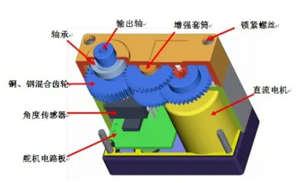
A servo motor is a simplified form of a servo control system. It typically consists of a DC motor, a reduction gear train, a potentiometer (position sensor), and a basic control circuit. Servo motors are widely used in low- to medium-precision applications, such as RC models and small robots.
The key differences between servo motors and industrial servo systems lie in their application scenarios, control accuracy, and system architecture. Industrial servo motors are designed for high-precision, closed-loop control in demanding environments, while common hobby and robotic servos prioritize simplicity and cost efficiency.
Different servo motor classifications emphasize different performance characteristics, such as control method, response speed, and load capacity. Selection should be based on application requirements:
Low-cost, simple control: Traditional PWM analog servos
High-precision dynamic control: Digital servos or bus servos
Continuous rotation applications: 360° servos
Multi-servo coordination in complex systems: Bus servos
Servo Type | Features | Applications |
PWM RC Servo Motor | Low cost with simple construction; limited interference resistance | RC aircraft, basic robots |
Serial Bus Servo Motor | Supports multi-device control; excellent anti-interference performance | Industrial automation, UAV gimbals |
Analog Control Servo | Slower response and noise-sensitive | Toy-grade RC models, simple control systems |
Digital Control Servo | High-speed response with precise control and programmability | Medical equipment, high-precision robots |
Plastic Gear Servo Motor | Lightweight and cost-effective, but limited torque | Small robots |
Metal Gear Servo Motor | Highly durable, but heavier | Industrial robotic arms |
2. Classification by Control Signal Type
2.1 Traditional PWM Servo Motors
Traditional PWM servos control the output shaft position by receiving a pulse-width modulation (PWM) signal. The pulse width determines the target angle, with a standard signal period of 20 ms. Typical pulse widths range from 0.5 ms to 2.5 ms, corresponding to 0° to 180° of rotation.
Key Characteristics
Analog servos respond more slowly and have weaker noise immunity; digital PWM servos offer faster response and higher precision.
Simple structure and low cost, but limited communication distance.
Typical Applications
RC aircraft control surfaces
Basic robotic joints
Steering systems in RC cars
2.2 Bus Servo Motors (Serial Bus Servos)
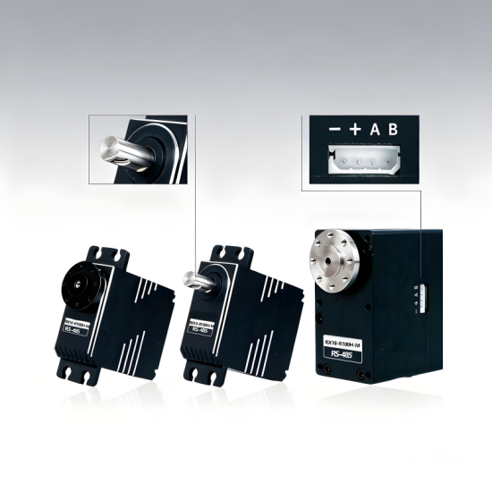
Bus servo motors, also known as serial bus servos, operate on principles similar to digital servos but integrate serial communication interfaces such as RS-485, CAN, I2C, or SPI. These servos communicate with a controller via a shared bus, enabling synchronized control and data exchange.
Key Characteristics
Supports multi-servo daisy-chain control with strong anti-interference capability and long communication distance.
Provides real-time feedback (temperature, load, position).
Supports advanced features such as closed-loop position control.
Higher cost and requires dedicated controllers.
Typical Applications
Industrial automation and robotic arms
UAV gimbal systems
Medical and surgical robotic equipment
3. Classification by Control Circuit Type
3.1 Analog Servo Motors
Basic Concept
Analog servos process control signals using analog circuitry and comparators to drive the motor.
Working Principle
The input PWM signal is compared with the potentiometer’s feedback voltage.
The resulting error signal drives the motor toward the target position.
Response speed is relatively slow and susceptible to electrical noise.
Key Characteristics
Slower reaction to small control signal changes.
Lower cost, but reduced long-term stability in noisy environments.
Typical Applications
Toy-grade RC models
Simple robotic motion control
3.2 Digital Servo Motors
Digital servos incorporate a microcontroller unit (MCU) and crystal oscillator to process control signals using digital algorithms, significantly improving accuracy and responsiveness.
Working Principle
The MCU samples input signals and feedback data at high frequency.
Optimized control algorithms determine motor drive behavior.
Supports advanced features such as stall protection and dynamic response tuning.
Key Characteristics
Fast response and high positioning accuracy.
Programmable parameters (speed limits, angle limits).
Some models support both servo and continuous motor modes.
Typical Applications
Industrial robots
UAV camera gimbals
Rehabilitation and assistive devices
4. Classification by Rotation Angle
4.1 180° Servo Motors
These servos have a limited output shaft rotation range, typically 0° to 180° (±90°), making them suitable for precise angular positioning.
Working Principle
Mechanical or software limits prevent over-rotation.
Ideal for fixed-angle positioning tasks such as robotic joints.
4.2 360° Servo Motors
360° servos allow continuous rotation, functioning similarly to DC motors but controlled via PWM signals for speed and direction.
Working Principle
Mechanical limits are removed, and the potentiometer is fixed at a constant resistance.
Pulse width determines behavior:
~1.5 ms: stop
<1.5 ms:="" rotate="" forward="">
>1.5 ms: rotate reverse
5. Classification by Application Domain
RC Aircraft Servos: Lightweight design with fast response for flaps and rudder control
Robotic Servos: High torque and precision for humanoid robots and robotic arms
Marine Servos: Enhanced waterproofing for RC boats
RC Car Servos: High vibration resistance for steering systems
6. Classification by Gear Material
Plastic Gear Servos
Lightweight and low cost
Suitable for low-load applications
Metal Gear Servos
Gears made from aluminum alloy or steel
High durability and torque capacity for demanding applications
Conclusion
Understanding servo motor classifications by control method, circuitry, rotation range, application domain, and material composition is essential for selecting the right servo for a given project. This knowledge helps engineers, hobbyists, and educators balance performance, reliability, and cost in robotics and automation systems.