Planetary Gearbox Transmission: Load Sharing Design, Verification, Faults, and Mitigation
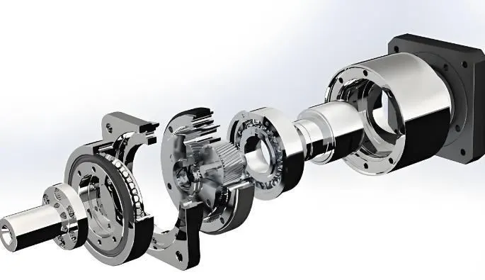
Planetary gearboxes are widely used in high-end equipment such as wind turbines, aerospace, heavy machinery, and automotive applications due to their compact structure, high transmission ratios, strong load capacity, and smooth operation. However, the optimal performance of a planetary gearbox largely depends on a key technology: load sharing.
This article provides a comprehensive overview of load sharing design principles, verification methods, common faults, and mitigation strategies in planetary gear transmissions.
1. Introduction to Load Sharing in Planetary Gears
1.1 What is Load Sharing?
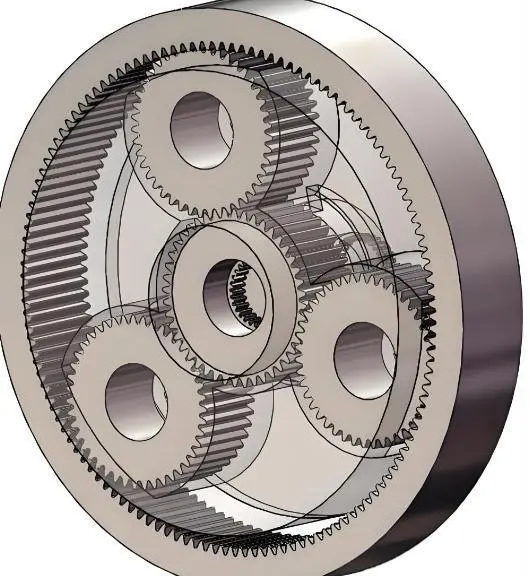
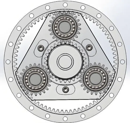
Ideally, in a planetary gear transmission, the input power is evenly distributed among multiple planetary gears, so that each gear carries the same load. This phenomenon is known as load sharing.
However, due to inevitable manufacturing errors, assembly tolerances, and elastic deformations under load, perfect load sharing is unattainable. The core objective of load-sharing design is to minimize uneven load distribution among planetary gears, thereby improving the gearbox’s load capacity, reliability, and service life.
1.2 Consequences of Uneven Load Distribution
Reduced load capacity: Individual planetary gears may become overloaded, creating weak points that prevent the gearbox from reaching its rated power.
Increased vibration and noise: Uneven load generates dynamic excitation forces, leading to higher vibration and noise levels.
Shortened service life: Overloaded gears may experience early pitting, adhesion, or tooth breakage.
Reduced reliability: Failure of a single planetary gear can trigger the collapse of the entire transmission system, causing severe operational risks.
1.3 Key Load Sharing Design Methods
Load sharing is primarily achieved through flexibility and floating components:
Floating Components: This is the most common and effective approach. By allowing certain components to have slight radial or axial movement, manufacturing and assembly errors can be automatically compensated.
Floating Sun Gear: Most widely used. The sun gear is designed with weak or no radial support, allowing it to self-align under planetary gear engagement. Achieved using splines or crown-shaped couplings.
Floating Ring Gear: Permits slight radial movement of the ring gear, commonly applied in wind turbine gearboxes.
Floating Planet Carrier: Less common but used in specific designs.
Load Sharing Mechanisms:
Flexible Pin Design: Planetary gear pins are designed as slender, flexible structures. When a planetary gear is overloaded, its pin bends slightly, transferring part of the load to other gears. This method is widely used in high-performance planetary gearboxes.
Self-Aligning Planet Bearings: Use of self-aligning roller bearings allows planetary gears to pivot slightly on their pins, compensating for meshing errors.
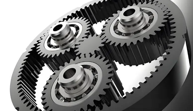
Manufacturing and Assembly Precision: The foundation of load sharing.
High-precision gear machining ensures accurate tooth profile and helix angles.
Planet carrier holes must meet strict position, coaxiality, and parallelism tolerances.
Dynamic balancing of high-speed carriers reduces imbalance loads.
Parameter Optimization:
Number of Planetary Gears: Typically 3–5 gears, balancing load-sharing performance with structural complexity.
Meshing Phase Design: Proper phase design of planetary gears helps cancel dynamic excitation forces, reducing vibration and uneven load distribution.
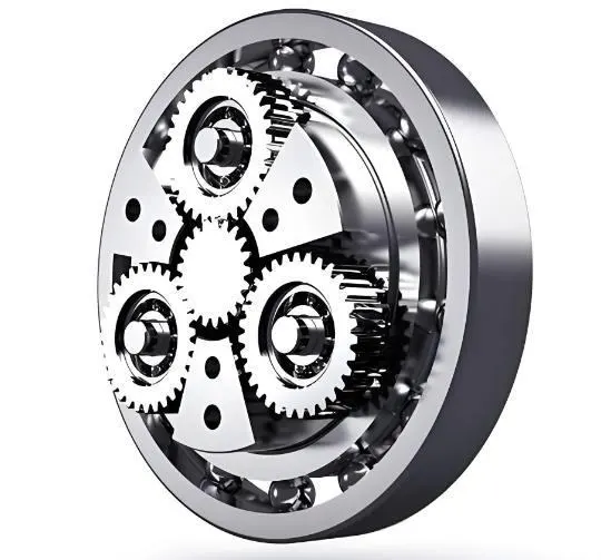
2. Verification of Load Sharing
After design, verification ensures the effectiveness of load sharing. Methods include theoretical calculations and simulation analysis.
2.1 Theoretical Calculation – Load Sharing Coefficient
The load sharing coefficient quantifies load imbalance:
Kγ=PavgPmax
Where:
Kγ = load sharing coefficient
Pmax = maximum load on a single planetary gear
Pavg = average load across all planetary gears
AKγ closer to 1 indicates better load sharing. Advanced designs often achieveKγ<1.05.<>
Calculations consider manufacturing errors (carrier indexing errors, pitch errors) and component flexibility (pin bending, gear deformation) using static force balance equations to derive load distribution.
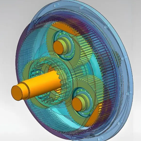
2.2 Simulation Analysis – Modern Design Tool
While theoretical models are simplified, modern CAE tools provide accurate and comprehensive verification:
Multibody Dynamics Simulation: Using software like Adams, Simpack, or RecurDyn, flexible models including gears, shafts, bearings, and splines simulate static and dynamic loads.
Finite Element Analysis: Using Abaqus or ANSYS, key components such as flexible pins and carriers are analyzed for stress, stiffness, and contact behavior under load-sharing conditions.
2.3 Experimental Verification
Load-sharing performance is ultimately confirmed through experiments:
Strain Measurement: Strain gauges on planetary pins or carriers measure load distribution during operation.
Tooth Root Stress Measurement: Patches or telemetry systems assess dynamic tooth root stress.
Vibration and Noise Analysis: Well-balanced gearboxes exhibit cleaner vibration and noise spectra with lower sideband amplitudes at meshing frequencies.
3. Common Faults and Mitigation
Even with careful design, planetary gearboxes may experience faults, often linked directly or indirectly to load-sharing failure. Mitigation strategies focus on design optimization, precise manufacturing, assembly accuracy, and proactive maintenance.
Failure Modes | Failure Symptoms and Causes | Mitigation Strategies |
Planetary Gear Tooth Breakage | Symptom: One or more teeth of a planetary gear are broken. | 1.Optimize load-sharing design: Use flexible pins or floating components. |
Gear Surface Pitting and Spalling | Symptom: Pitting or large material spalling on the gear surface. | 1.Enhance load-sharing performance to reduce maximum contact stress. |
Planetary Gear Bearing Failure | Symptom: Bearing cage breakage, raceway peeling, burning damage. | 1.Improve load distribution from the source to eliminate misalignment. |
Planet Carrier Cracking | Symptom: Cracks or fatigue fractures appearing on the planet carrier or its connection points. | 1.Optimize planet carrier structure using smooth transitions to reduce stress concentration. |
Sticking of Floating Components | Symptom: Sun gear or internal ring gear unable to float properly. | 1.Reasonably design spline fit clearance and lubrication. |
4. Conclusion
Load-sharing technology in planetary gearboxes spans the entire lifecycle, from design and manufacturing to assembly and operation:
Design is key: Innovative approaches such as floating components and flexible pins establish load-sharing capability.
Verification ensures reliability: Theoretical and CAE tools precisely predict and validate load-sharing performance.
Manufacturing and assembly are foundational: High-precision machining and strict assembly standards ensure the design intent is realized.
Operation and maintenance are critical: Proper lubrication, condition monitoring, and scheduled maintenance prevent load-sharing failure and catastrophic faults.
Only by integrating these four aspects can planetary gear transmissions achieve high efficiency, reliability, and long service life, unlocking the full potential of high-end transmission equipment.