Motor Sizing Guide: How to Calculate Motor Power for Linear and Rotary Motion
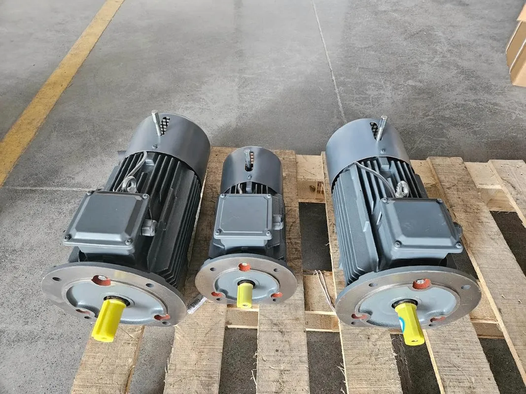
Correct motor sizing is critical for ensuring system reliability, efficiency, and long service life. An undersized motor may stall or overheat, while an oversized motor increases cost and reduces overall efficiency.
This motor sizing guide explains how to calculate motor power for both linear motion and rotary motion, including transmission efficiency, safety factors, and common motor selection mistakes.
Determine the Type of Motion
Motor power calculation depends on whether the system uses:
Linear motion (ball screw actuators, belt-driven slides, lifting platforms)
Rotary motion (turntables, winding machines, rotating shafts)
Each motion type requires a different motor sizing formula.
Motor Power Calculation for Linear Motion
Linear motion systems are widely used in industrial automation, CNC machines, and lifting equipment.
Basic Formula
The theoretical mechanical power is:
P = F × V
Where:
P = Power (W)
F = Force or thrust (N)
V = Linear speed (m/s)
This equation represents ideal mechanical power only. For practical motor selection, transmission efficiency and safety factor must be included.
Correct Motor Sizing Formula for Linear Motion
P_motor = (F × V × K) / η
Where:
η = Transmission efficiency
K = Safety factor (typically 1.2–2.0)
Typical Transmission Efficiency Values
Ball screw: 0.85–0.92
Timing belt: 0.80–0.90
Gear transmission: 0.90–0.95
Why Efficiency Matters in Motor Selection
Mechanical losses such as friction, belt slip, and gear meshing reduce usable output power. Ignoring efficiency is one of the most common mistakes in motor power calculation.
Additional Consideration: Acceleration Force
During acceleration, the motor must overcome both the steady-state load and inertial forces. In high-speed or reciprocating systems, acceleration torque can exceed constant-load torque.
For accurate motor sizing, acceleration requirements must be included.
Motor Power Calculation for Rotary Motion
Rotary systems require torque-based motor selection.
Standard Power Formula
P = T × ω
Where:
T = Motor torque (N·m)
ω = Angular velocity (rad/s) = 2πn / 60
n = Rotational speed (rpm)
In practical engineering calculations, the formula is often written as:
P (kW) = T (N·m) × n (rpm) / 9550
This formula is commonly used in motor torque calculation and gearbox design.
When to Use the Rotary Formula
Direct-drive applications
Gear-reduced systems
Situations where torque and speed are known
This method is typically used for detailed verification rather than rough estimation.
Common Motor Sizing Mistakes
Even when applying the correct motor sizing formula, selection errors can occur.
1. Ignoring Transmission Efficiency
Always divide by efficiency:
P_motor = (F × V) / η
2. Ignoring Acceleration Inertia
Dynamic systems require additional torque during acceleration. Neglecting inertia can lead to motor overheating or failure during startup.
3. Ignoring the Safety Factor
Load variations, friction changes, and unstable operating conditions can cause temporary power spikes. A safety factor between 1.2 and 2.0 is generally recommended.
Recommended Motor Sizing Formula
For most linear motion systems, the practical motor power calculation formula is:
P_motor = (F × V × K) / η
This corrected approach improves motor selection accuracy, prevents undersizing, and enhances system reliability.
Final Thoughts on Motor Selection
Accurate motor sizing requires more than applying a single equation. Engineers should evaluate:
Motion type
Transmission efficiency
Acceleration requirements
Safety factor
Duty cycle
A structured motor sizing process ensures optimal performance, cost efficiency, and long-term operational stability.