Core Requirements for Motors in Humanoid Robot Joints
Humanoid robots are at the cutting edge of robotics technology, and designing motors for their joints presents unique technical challenges. Unlike traditional applications such as industrial automation and automotive systems, humanoid robots have more stringent and complex motor requirements. This article systematically discusses the design demands and optimization methods for humanoid robot joint motors from three core perspectives: power density, temperature rise control, and cogging torque.
1. Power Density
Power density is a key indicator of motor performance, reflecting the ability to achieve maximum power output within a confined space. For humanoid robots, the power density requirement can be broken down into three key aspects:
1.1 Size Constraints
The space available for humanoid robot joints is extremely limited, imposing strict constraints on motor dimensions:
Outer Diameter: The outer diameter of most joints is limited to around 120mm, with smaller joints like wrists and elbows typically limited to 80-90mm. This limitation stems from the bionic design philosophy, where robot joints must mimic the proportions of human joints.
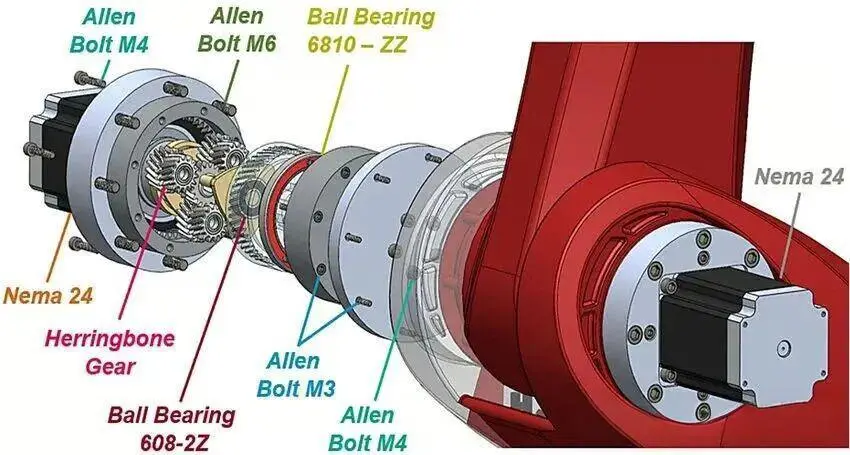
Axial Length: Humanoid robot joints adopt a highly integrated "stacked" structure, where components such as the motor, reducer, sensors, and drivers are stacked together. As a result, the motor’s axial length must be minimized to make room for other essential components.
Hollow Diameter: The joints need to reserve space for hollow channels, which serve purposes such as routing signal and power lines, housing ball screws in straight joints, and providing a channel for the input shaft of planetary reducers in rotating joints. These constraints result in the characteristic "hollow and flat" structure of humanoid robot joint motors.
1.2 Lightweight Requirements
Power density fundamentally reflects the power output per unit volume or mass. Since humanoid robots are mobile platforms, their overall weight directly affects performance and energy efficiency. Therefore, motor designs must minimize weight while ensuring adequate power output. This requires systematic design optimization in areas such as material selection and structural optimization, such as using high-strength aluminum alloy casings and optimizing the magnetic circuit to reduce core material usage.
1.3 Overload Torque Capacity
Humanoid robots frequently perform rapid acceleration and deceleration actions, often with significant load inertia. This places strict demands on the motor’s instantaneous torque output capacity:
Overload Multiplier: Industry standards require motors to handle overloads of 3-5 times the rated torque. For example, a motor rated at 10Nm should be capable of outputting a peak torque of 30-50Nm for short durations.
Overload Duration: The duration for which the motor can sustain peak torque typically needs to be between 3-10 seconds, covering most dynamic movements like rising quickly or jumping and landing.
1.4 Power Density Optimization Methods
To meet the above requirements, engineers employ several design strategies:
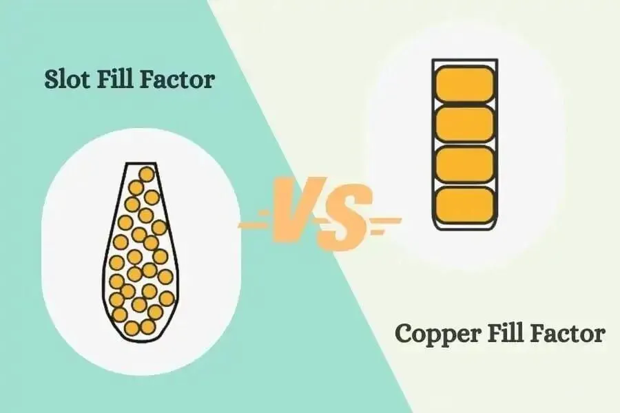
Slot Fill Factor Improvement: Maximizing the copper fill in the stator slots increases the space utilization. Using flat wire winding, segmented winding techniques, and other methods can raise the slot fill factor from the traditional 40-50% to 60-70% or even higher.
Electromagnetic Topology Optimization: Using finite element simulations to optimize parameters such as stator tooth shape, air gap length, and pole-slot matching increases torque density and overload capability without increasing motor volume.
High-Performance Permanent Magnets: Humanoid robot motors typically use high-grade Neodymium Iron Boron (N52) permanent magnets. These rare-earth magnets generate strong magnetic fields in small volumes. While expensive, they are essential for high-performance applications.
Segmented Magnet Design: Dividing the permanent magnets into smaller pieces not only increases the number of pole pairs to enhance torque but also reduces eddy current losses within the magnets, improving motor efficiency.
2. Temperature Rise Control
Temperature rise control is a critical challenge in humanoid robot joint motor design. Compared to traditional applications, humanoid robots face unique heat dissipation issues:
2.1 Special Heat Dissipation Environment
Floating Base Issue: Industrial robots are typically fixed to the ground or a workbench, allowing effective heat dissipation through their base. In contrast, humanoid robots are mobile platforms, and their joints are suspended, making it impossible to utilize a fixed base for heat dissipation.
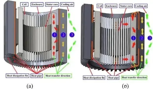
Limited Heat Dissipation Paths: Humanoid robot joints can only dissipate heat through two methods: natural convection of air (which is inefficient) and heat conduction through joint structural components (which has limited paths). Traditional active cooling methods like forced air cooling or water cooling are difficult to implement on humanoid robots, making temperature rise control a significant challenge.
2.2 Heat Generation Analysis under Key Operating Conditions
Stall Condition: When the robot maintains a specific pose or carries a load without movement, the motor operates in a stall condition. During this state, the motor outputs a constant torque but with zero speed, causing all electrical energy to be converted into copper losses, which leads to significant heat generation. Copper loss can be calculated using the formula:
Pcopper loss=I2×R,
whereI is the phase current, andR is the winding resistance.Dynamic Condition: During robot movement, the motor’s speed and torque vary. While the instantaneous operating condition may not be the worst case, the equivalent rated condition must be considered. Under dynamic conditions, both copper losses and iron losses (eddy current losses and hysteresis losses) contribute to total losses:
Ptotal=Pcopper loss+Piron loss=I2R+Peddy+Physteresis.
2.3 Systemic Effects of Temperature Rise
Excessive temperature rise can cause a chain reaction that affects the entire joint module's performance:
Reducer Performance Degradation: High temperatures can cause a decrease in the viscosity of the reducer’s lubricating grease, impairing lubrication and accelerating gear wear, thus shortening the reducer’s lifespan.
Electronic Component Reliability: The PCB boards, power modules, and other electronic components integrated into the joint are temperature-sensitive. For every 10°C increase in temperature, the failure rate of these components approximately doubles.
Mechanical Precision Loss: Thermal expansion caused by temperature changes can lead to structural component deformation, affecting the stability of sensor zero points and mechanical transmission accuracy.
2.4 Temperature Rise Optimization Methods
Current Density Control: Current density is a key parameter that determines the extent of heating in the windings. It is defined as the current per unit conductor cross-sectional area:
J=AI,
whereJ is the current density (A/mm²),I is the current (A), andA is the conductor cross-sectional area (mm²). Ideally, current density should be kept below 8 A/mm², though small joint motors may reach 12-15 A/mm².Reducing Winding Resistance: By increasing conductor cross-sectional area, using thicker copper wire, and increasing the number of turns in the winding, the total resistance can be reduced, thus decreasing copper loss and heat generation.
Application of Ultra-Thin Silicon Steel Sheets: Humanoid robot motors often use silicon steel sheets that are thinner than the conventional 0.35-0.5mm. Using 0.2-0.25mm thick sheets reduces eddy current losses significantly, as eddy current losses are proportional to the square of the sheet thickness.
Epoxy Resin Encapsulation: Epoxy resin can be used to encapsulate the motor’s end caps and slots, improving heat transfer to the shell. The resin solidifies to form a cohesive structure, enhancing both heat dissipation and mechanical strength.
Magnetic Circuit Optimization: By optimizing the stator-rotor magnetic circuit structure, reducing magnetic reluctance, and minimizing flux leakage, motor efficiency is increased, leading to lower heat generation.
3. Cogging Torque: Key to Smooth Operation
Cogging torque is a physical phenomenon inherent in permanent magnet motors and has a decisive impact on the smoothness of humanoid robot movement.
3.1 The Physical Nature of Cogging Torque
Cogging torque arises due to the interaction between the stator tooth slots and the rotor’s permanent magnets. As the rotor moves, the magnetic field changes periodically, causing the system to tend to stop at the positions of minimum magnetic reluctance, creating torque pulses that impede or aid rotation.
3.2 Performance Impact of Cogging Torque
Humanoid robots require strict control of cogging torque, usually limiting its peak to 2-3% of the rated torque, with high-end applications demanding a reduction to 5‰. High cogging torque leads to:
Motion Smoothness: Cogging torque causes speed fluctuations, leading to periodic jerks in joint movement. This not only affects motion accuracy but also induces structural resonances that may damage mechanical components.
Control System Challenges: As a periodic disturbance, cogging torque adds extra burden to the servo control system. While advanced control algorithms can compensate for it, hardware-level optimization is more crucial.
3.3 Cogging Torque Optimization Methods
Pole-Slot Combination Optimization: By choosing appropriate pole and slot combinations, cogging torque at different positions can cancel each other out. The least common multiple principle ensures the smallest possible cogging torque.
Fractional Slot Winding: Using fractional slot designs ensures that the stator’s slot-to-pole ratio is fractional rather than integer, further reducing cogging torque.
Stator Slot Shape Optimization: Cogging torque is directly influenced by the shape of the stator slots. Optimizing slot width, tooth tip shapes, and chamfering can smooth out the magnetic field distribution, reducing cogging torque by 30-50%.
Permanent Magnet Shape Design: The shape of the permanent magnet affects the air gap’s magnetic field distribution. Common magnet shapes include:
Rectangular Magnets: Simple to process but result in high harmonic content.
Bread-shaped Magnets: Have an arc-shaped surface, resulting in a smoother magnetic field.
Wedge-shaped Magnets: Best fit the stator’s inner circle, providing optimal magnetic field distribution.
Slanted Pole Design: By tilting the stator teeth or rotor poles along the axial direction, cogging torque from different axial positions can be phased out, further reducing cogging torque.
3.4 Key Issues in Engineering Practice
There is often a significant gap between theoretical design and actual testing. For instance, electromagnetic simulations may predict cogging torque as 1% of the rated torque, but measured values may reach 10%. This discrepancy is mainly due to manufacturing and assembly tolerances:
Stator-Rotor Cylindrical Accuracy: Errors in the roundness of the stator inner circle or rotor outer circle cause uneven air gaps, increasing cogging torque.
Concentricity Errors: Radial runout after stator-rotor assembly leads to uneven air gaps along the circumference, exacerbating cogging torque.
Core Lamination Quality: Misalignment or warping of silicon steel sheets during lamination can lead to inconsistent slot shapes, increasing cogging torque.
Therefore, when aiming for low cogging torque in practical applications, strict control over machining precision and assembly processes is essential.
4. Systematic Design Philosophy
The three core indicators mentioned above—power density, temperature rise, and cogging torque—are interconnected and interdependent. Excellent motor design requires finding an optimal balance between multiple objectives:
Power Density vs. Temperature Rise: Increasing power density means fitting more copper wire and using stronger magnets, which increases current density and heat generation. Temperature rise control requires minimizing losses and improving heat dissipation, but this competes for valuable space.
Cogging Torque vs. Torque Output: Many measures to reduce cogging torque (such as slanted poles or magnet shaping) reduce effective magnetic flux, leading to lower torque output. Therefore, it's crucial to balance the reduction of cogging torque with the required torque output.
Cost vs. Performance: High-grade magnets, ultra-thin silicon steel sheets, and precision machining significantly increase costs. Commercial products must balance performance with manufacturing costs while meeting necessary specifications.